Web farms in .NET and IIS part 4: Code deployment

So now we have our web farm in place where the servers in the cluster are identical machines: they have the same CPU, same RAM, same OS etc. This is an important point as you certainly want to provide the same user experience regardless of which web farm server receives the web request.

A good way to ensure this is through using templates in a virtualisation environment, such as VMWare. You define a template for a model machine with all the necessary physical traits such as the CPU, disk size, RAM etc. You then use this template to create new virtual machines. This process is a lot smoother and cheaper then buying new physical machines.

The next step is code deployment. You typically want to deploy your website on all machines in the farm, right? You can of course manually copy over your deployment package to each and every server one by one but that’s inefficient and tedious. A staging server can help you out.

Staging server

A staging server is not part of the web farm therefore it won’t get any web requests. However, it will also have IIS installed just like the machines in the web farm. We can first deploy our code to that IIS and we can use that IIS to deploy the website to the web farm servers. The staging server can act as an environment where we check if our code is working properly, if the configuration is working fine etc. It is the last stage before actual employment so ideally the staging server has the same physical properties – CPU, RAM, etc. – as the servers in the web farm:

Staging server

There’s a free tool from Microsoft that you can use to deploy your code: MSDeploy, or Web Deploy. MSDeploy is a command line tool that Visual Studio uses behind the scenes if you choose that deployment method when publishing your code. It can be used to migrate IIS configuration, web content, Windows components. It is a powerful tool which is well suited for web farms because it allows to synchronise some more difficult items such as the registry or the GAC.

Demo

Open Visual Studio 2010 or 2012 and create a new MVC internet application. I will go through the steps using VS 2012 but web deployment is available in VS 2010 as well. You can leave the default website content as it is, we’re only interested in the deployment options. You can open the publish options from the Build menu:

Publish web menu point

This opens the Public Web window:

Publish Web window

In the Select or import a publish profile drop down list select New… Give some meaningful name to the deployment profile:

Give name to deployment profile

You can then select the deployment method:

Deployment method option selector

The Web Deploy publish method represents the MSDeploy tool mentioned above. Like in parts 2 and 3 of this series I don’t have access to any private web farm so I’ll just deploy this web site to the IIS instance of my own computer.

UPDATE: in this post I show how to set up Web Deploy with a real external web server.

Open the IIS manager and add a new web site:

Add application IIS

Give it some name and select the physical location of the deployment package. You can create a new folder using the Make New Folder button.

Back in VS we can now specify the server as localhost and define the application name which we’ve just set up:

Web deploy options

You can validate the connection using the Validate Connection button which requires that you start VS as an administrator.

The Service URL can be the location of your staging server or that of a hosted environment that you’re deploying your site to: http://staging.mysite.com, http://finaltest.mysite.com or whatever URL you gave that IIS website. Press Publish and you may be greeted with the following error message in VS:

Web deployment failed due to wrong runtime version

Back in IIS we need to modify the default application pool that IIS created automatically for the new web site:

Default application pool in IIS

Right-click that application pool and select Advanced settings from the context menu. Change two things in the Advanced Settings window:

Modify application pool in IIS

Run the deployment from VS again and it should proceed without errors:

Web deploy success

You can even check the contents of the deployment folder you specified in IIS to verify that the web site was in fact deployed:

Deployment package in folder

You can even see the same structure in IIS under the website:

Web site contents in IIS

In a real life environment we would check this code into source control, such as GIT or SVN. The staging server would pull out of source control the latest check-in code but for now we’ll just pretend that this localhost environment represents our source control server. So we’ll push this code to our staging server thereby doing what a source control would do for us automatically.

The msdeploy tool is normally located at C:/Program Files/IIS/Microsoft Web Deploy V3. At the time of writing this post V3 was the latest available version. By the time you read this there may be a newer version of course. Open a command prompt, navigate to that directory and run msdeploy.exe without any arguments. You should get a long list of options that msdeploy can be used with:

MSDeploy options in command window

We can write a short batch file to carry out the necessary msdeploy commands for our deployment purposes. In the batch file, which we can call deploy.bat we first specify the directory:

cd “\Program Files\IIS\Microsoft Web Deploy V3”

Then we can fill up the file with msdeploy commands. To deploy from the current location, i.e. localhost, to our staging environment, we can write like this:

msdeploy -verb:sync -source:iisApp=mysite.com -dest:iisApp=mysite.com,computerName=[name of staging server machine]

We’re instructing msdeploy to pull the code out of mysite.com on the local machine and deploy it to mysite.com on the staging server. This command will simply take the contents of the mysite.com website and push it over to the given destination.

Then from there it’s equally straightforward to deploy to our web farm machines:

msdeploy -verb:sync -source:webServer,computerName=[name of staging server machine] -dest:webServer,computerName=[name of first machine in web farm]
msdeploy -verb:sync -source:webServer,computerName=[name of staging server machine] -dest:webServer,computerName=[name of second machine in web farm]

So here we don’t just copy the application itself but the entire IIS config and its contents from the staging server and push it over to the web servers one by one. We’re taking the staging server and push it out to farm machine 1 and 2.

We do this because we want to make sure that the web farm machines have the exact same IIS configuration as the staging one. Remember that we can run tests on the staging server where we fine-tune some IIS settings, like response headers or whatever, and we want those settings to be copied over to all live web servers. We want this to ensure that every member in the farm behaves the same, i.e. the end users get the same behaviour. If we only copy the application contents from the staging machine to the web farm machines then it’s not guaranteed that the IIS settings across the web farm will be the same as on the staging machine.

In other words the staging server is a central place in the system. It is a blueprint for all live web servers in the web farm: the code, the configurations, the IIS settings etc. available on the staging server are the ones that take precedence. It represents the most recent stage of the deployment environment. You shouldn’t go out and change the settings on the web farm servers and hope for the best. Instead, you “play” with the staging server settings and when you’re satisfied with the results you can push out the entire IIS config and its contents to the web farm.

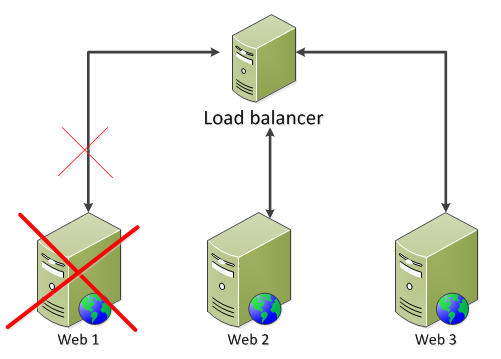
If you want to get really advanced then you can employ a PowerShell which pulls out the web server from the farm just before deploying the code to it to make sure that this machine doesn’t get any traffic during the deployment process. The script would do this to every machine in the farm one by one.

Other content replication tools

MSDeploy is by no means the only tool to replicate content. You can check out the following alternatives:

  • Distributed File System (DFS)
  • Robocopy
  • Offline folders
  • Web Farm Framework

DFS is a solution to keep servers in sync. It consists of two parts: DFS Namespaces (DFSN) and DFS Replication (DFSR). They make up a powerful tool to achieve high availability and redundancy. DFSN ensures that if one server fails then another takes over without any configuration changes necessary. DFSR on the other hand gives you the ability to replicate content over either a LAN or a WAN.

Robocopy – Robust File Copy for Windows – is a command line tool by Microsoft that will replicate content between servers, either one-way or two-way. Its main advantage is the easy-to-configure replication between folders. However, it doesn’t offer a method to redirect to the backup server is the primary server fails. With DFS this is possible to achieve.

The next option, i.e. offline folders, is rather a tool to enable the usage of offline folders which offers faster performance when the network is slow and offline files when the network is completely down. The result is that configuration files will always be available even in the case of network problems. This technique is known as Client Side Caching (CSC): in case of a network failure IIS will use the cached version until the network connection is restored.

We mentioned the Web Farm Framework in the first part of this series: it’s an advanced plug-in to IIS made by Microsoft which can fully automate the content replication tasks. We’ll take a closer look at WFF in an upcoming post.

Web farms in .NET and IIS part 3: Application Request Routing ARR

Introduction

In this post we’ll look at the basics of Application Request Routing. The target audience is beginners who have not worked with ARR before and want to get going with it.

As mentioned in the first post of this series ARR is an extension that can be added to IIS 7.0 and above.

ARR has a lot more available functions than Network Load Balancing (NLB) making it the better load balancing option. However, ARR doesn’t have its own solution for high availability so it cannot handle failures to the server hosting ARR – the result is that the ARR server becomes a single point of failure. This is where NLB enters the scene as it provides high availability – ARR and NLB together make up a very good team.

ARR comes with the following advantages compared to full-blown hardware based load balancers:

  • Cost: if you have IIS7.0 or above you can install ARR free of charge
  • Ease of use: this is of course relative, but if you have some basic knowledge of IIS then the learning curve will be minimal
  • Performance: ARR can handle very large sites with ease – the first resource limit that ARR runs into is network. Most networks support 1 Gbps or more, so this is usually not an issue
  • Flexibility: ARR offers load balancing based on any server variable, URL, cookie etc.

ARR has some disadvantages:

  • As mentioned above ARR doesn’t have its own built-in solution for high availability
  • It does not offer the same range of features as more complete hardware based products. E.g. it lacks SEO treatment and DDoS handling. Some of these shortcomings can be solved with other products, such as NLB or Request Filtering

You can get pretty far with NLB and ARR unless you have some very specialised needs that only expensive commercial products can provide.

ARR is a software based reverse proxy solution – for an explanation of these terms check out the first post in this series. It supports all common load-balancing algorithms, such as server weighting, round-robin etc. The following general list shows the features available in ARR:

  • Health checking
  • Caching
  • Can work as a Content Delivery Network (CDN)
  • SSL offloading
  • HTTP compression
  • URL rewrite
  • Usage reporting
  • Sticky sessions
  • Programming and automation support

ARR only handles HTTP traffic, so it cannot work in conjunction with FTP, RDP etc.

Routing

ARR routing goes through three touchpoints:

  1. IIS site binding: your website will of course need to have a valid URL which we can call the ARR base. It is a site that appears below the Sites node in the IIS manager
  2. URL rewrite rule: this happens at the IIS level
  3. The server farm

When a web request hits the ARR server it is first caught by the IIS binding. A standard binding needs to exist on a website. This is the same process as setting up a new website in IIS under the Sites node. It can be a generic website with no real content – it is only used for the HTTP and HTTPS bindings. Also, it is here where SSL offloading occurs.

The request is then caught by URL Rewrite as long as an appropriate rule exists. This happens at the PreBeginRequest step in the IIS pipeline so it is performed before any other site functionality. URL Rewrite rules can edit server variables as well.

In the last step the server farm gets the request from URL Rewrite. It determines which server to send the request to based on the load balancing algorithm and client affinity settings.

How-to

You can download ARR on your designated routing server using the web platform installer available here. Search for Application Request Routing in the search window of the installer and select the below version:

ARR in web platform installer

By the time you read this post there may of course be a new version of the extension.

Click Add and Install in the installer window. The installer will fetch all the dependencies as well.

As in the case of Network Load Balancer I don’t have a private network of Windows servers. Therefore I can show you the steps you need to take in order to create a web farm but will not actually create one in the process.

As soon as you install ARR you will see a new node called Server Farms in the IIS manager:

Server farms node in IIS

Right click on that node and select Create Server Farm. The Create Server Farm window will appear where you can add the Server farm name:

Create server farm window

You can provide any name here, like in the case of the, but give it some URL-type of name, such as arr.mysite.com. It’s a good idea to provide the same name as the URL for the ARR version of your website. Example: if your website is http://www.fantasticsite.com then the ARR version may well be arr.fantasticsite.com. Click Next to go to the Add Server window:

Add Server window in ARR setup

Here you can add the servers that are the members of the farm. Add the server address one by one in the Server Address textbox and click Add after each entry. The servers you will appear in the list box. Click Finish when you’re done with this step. ARR will then ask you if you want to create any URL rewrite rules:

Ask if URL rewrite rules should be added

Click yes. You’ll see that the server farm will appear in the Server Farms list of the IIS manager. Open the Server Farms node, select the name of the farm you’ve just created and you will see some additional setup options:

Server farm setup options in IIS

The default options are sufficient to test the network. Open a web browser and navigate to the ARR name of your website such as arr.mysite.com. The request should be routed to one of the web farm members you specified during the setup.

Let’s look at some of the options in the IIS manager. Clicking on Caching will open the following window:

Caching options window ARR

The default setting is that anything that goes through ARR will be cached for 60 seconds and disk cache is enabled. So if 2 web requests ask for the same resource within a minute ARR will hand back the cached version to the second request without consulting the web tier. You can even set whether the caching mechanism should cache the results by the query string or not. Example: arr.mysite.com?arg=1 and arr.mysite.com?arg=2 will probably return different results from your backend database so it’s a good idea to cache by the query string.

So what is cached? ARR follows the caching rules set out in RFC2616. By default all static content such as css, js etc. is cached.

If your site streams media then checking the Enable request consolidation checkbox can be a good idea. It will consolidate all the streaming requests to reduce the number of requests.

Also, it is recommended to turn off the idle time setting of the application pool:

Idle time out in IIS

By default this value is set to 20 minutes. This means that the application pool will enter “sleep” mode if it sits idle, i.e. receives no web request for 20 minutes. Set that value to 0 to turn off this feature, which is recommended anyway, so not only in web farm scenarios. This keeps your site actively running while maintaining the health checking even during quiet times.

ARR can even function as a Content Delivery Network to front entire web farms. Check out the resources on this page for a video user guide.

The Health Test window looks as follows:

Health test window ARR

Here you can schedule explicit health checks and/or rely on live traffic tests. Live traffic testing watches for errors with the live traffic. If it sees what you define as a failure it marks that server as unhealthy. The main advantage of this method is that is watches for errors with any type of page request not just a single testing URL. The main disadvantage is that if the developers release a bad, untested version of the website then eventually all web farm machines may be turned off as all of them may eventually produce the same error if the same page is requested by the clients. This makes a DoS attack a breeze and even completely innocent clients can break down your site if they hit F5 often enough. Also, if a live traffic test shuts off a web server then that server is not brought back online automatically. Therefore it’s very important that you set up explicit URL testing as well and don’t rely on live tests exclusively.

You can configure live traffic tests as follows:

  • A comma separated list of failure codes that will cause the web server to be marked as unhealthy. You can even define a range with a hyphen, e.g. 400-500, or mix the styles such as 500, 510-599
  • The number of maximum failures that must occur during the failover period before the server is marked unhealthy
  • The failover period in seconds is used along with the maximum failures to determine if there are too many failures during the failover period. If this value is set to 0 then live traffic testing is disabled.

With explicit URL testing you ask ARR to send a request to the web farm members with specific time intervals and inspect the response. You can provide the URL in the URL text box. The test request will be sent to each machine in the farm. It’s highly recommended that you set up explicit URL checks so that unhealthy servers are not allocated any web requests. You can enable explicit URL tests by providing a URL in the appropriate text box. We’ll come back to this type of test a little later, but here are the parameters you can set:

  • The test URL whose response is inspected by ARR
  • The time between tests in seconds – if the test fails ARR will continue to send the same request and bring the server back online if the test passes
  • The timeout in seconds before the health test gives up on a page that takes too long. If ARR receives no response before the timeout then the server is marked as unhealthy.
  • The Acceptable status codes field works the same way as failure codes in the case of live traffic tests
  • You can also perform a content match to ensure that a certain word or phrase can be found on the page.

Bear in mind that ARR will mark the server as unhealthy after the very first bad response. Therefore make sure that the testing interval is not too long as even fully functioning and healthy servers may produce bad responses from time to time.

In the bottom of the same window you’ll see another text box where you can define the number of minimum servers. The idea here is that if you know that you need a certain number of healthy servers to reasonably handle the load then the health test shouldn’t allow the server farm to drop below that level. Example: your web farm has 10 machines and you need a minimum of 6 to handle the load on an average day. If the number of healthy servers drops to 5 then it may be a better idea to bring all machines back online again: 5 out of 10 users will receive good experience, so not all visitors will be impacted. The quality level is difficult to predict: your users may see intermittent errors that only occur if their request is directed to one of the bad servers. This is a tradeoff: the web farm will not be rendered completely useless due to overloading but the user experience may not be top class either. If this limit is reached then ARR will ignore all scheduled tests and bring back all servers online again.

The test URL should be a very simple self-contained page: it should not access the database or your application logic. If your database or application layer fails then all the web farm machines will be taken out of action. The ideal test page contains only some static HTML. Make sure that the test page only fails if there’s a problem with the specific server the page is employed on. Otherwise, if the test page fails on every server then the entire web farm will be useless as all servers are brought offline.

You can pick the load balance algorithm in the Load Balance window, meaning how would like to set the rules for web request routing:

Load balance algorithm options ARR

The default option is Least current request which is probably the most logical choice. This option means that the web request will be routed to the web farm member that has the least amount of request. Weighted round robin tells ARR to route the requests to each web farm member in turn: first to server 1, then 2 then 3, back to 1, then 2, then 3 etc. regardless of the current load each machine. You can find the explanation of each algorithm in the first post of this series.

If you change the default options you’ll need to select Apply to the right:

Apply changes to ARR in IIS

The Monitoring and Management window will show you the web request statistics and current health state of each member of the web farm:

Monitoring and management ARR in IIS

You can even get some real time disk cache statistics in the bottom of this window:

Real time disk cache stats ARR

Proxy allows us to configure how the packets are forwarded:

Proxy settings ARR

Preserving the X-Forwarded-For header can be useful if you want to see which IP the client’s request originated from.

In the Routing Rules window we can set various advanced features.

Set routing rules ARR

You can e.g. let the ARR server take care of SSL encryption and decryption by selecting the Enable SSL offloading option which is set by default. Keep in mind that ARR is a reverse proxy load balancer meaning that the web farm servers will see the http request coming from ARR and not from the client. If ARR is responsible to encrypt and decrypt SSL then the web farm will get HTTP requests from ARR even if the original request was sent through HTTPS. If it is critical in your environment that the web farm receives HTTPS requests then a tool called ARR Helper can be something to consider: it digs out the details of the original HTTPS message from the ARR server and writes them back to the original locations thereby fooling the web servers into thinking that the request came from the client in the form of HTTPS. The tool can be downloaded from this link. It comes in two versions: 32bit and 64bit. The tool must be installed on the web servers, not on the ARR machine.

In the Server Affinity window you can set whether you want sticky sessions or not.

Server affinity window in ARR

The default setting is that there are no sticky sessions. Selecting Client affinity means that the same user will be directed to the same machine during the web session. Session stickiness will be cookie based, you can even set the name of the cookie in the Cookie name text box.

With the web farm and the load balancer in place you can test how ARR behaves if one of the web farm servers is taken out of action. Go to the IIS manager of a server and stop the application pool of the website deployed there:

Stop application pool ARR web farm

If you selected the round robin routing algorithm then you will see the following: a normal 200 response from the web server still up and running followed by a 503 from the one you’ve just shut down, then back to healthy server, then again to the inactive one etc. We can set up a status check to avoid this behaviour so that ARR can determine if a web server is healthy before routing any web requests to it.

Go back to ARR and select the Health checks option. Enter a URL which ARR can send requests to. It can be a page dedicated to the health checks, a very simple page with no value to a “real” visitor. Its only reason to exist is to check the state of the web server. How you implement such a logic is up to you, e.g. check if the page can connect to a web service. The outcome of that logic should be a simple boolean value: is this web server in a healthy state or not.

Then you can set the interval for the health checks in seconds:

Set interval of scheduled health checks

Note that these checks are real web requests so it creates some additional load on your web site. Therefore make the status URL as lightweight as possible.

Then you can set the upper limit of the response timeout and the acceptable status codes as well. The response match text box has the following purpose: say that your status page writes a specific string in the response if the status is fine, such as “True” or “Success”. You can put that string in this text box. If the response from the status page is different from this string then the machine is deemed unhealthy.

You can test the status response by pressing the Verify URL test button:

Verify URL test button ARR

If you again turn off the application pool of one of the farm members then you should see that ARR does not route any traffic to that server. Also, the Monitoring and Management window should tell you that the server is not healthy:

Unhealthy server in web farm

High availability for ARR

As mentioned before ARR doesn’t have any built-in high availability feature. If the ARR server is down then the web farm will be unavailable. This doesn’t sound too convincing as one of the reasons we set up web farms is to ensure high availability, right? One solution is to go for a full-blown hardware based commercial load balancer but those typically cost a lot of money. If you are looking for a cheaper alternative then Network Load Balancing (NLB) can be useful. NLB is a load balancer with limited capabilities but can be used together with ARR. NLB must be installed and configured on the web servers of the farm. See the previous post on NLB.

This concludes our discussion on the basics of ARR.

Web farms in .NET and IIS part 2: Network Load Balancer

This post is direct continuation of the post on the general introduction into web farms. We briefly mentioned NLB in the previous post: it performs load balancing by manipulating the MAC address of the network adapters.

This product is in fact not the primary choice for load balancing nowadays. It is very easy to use but it lacks many features that a full blown load balancer has but it has its place, especially in conjunction with Application Request Routing ARR – more on that in the next post.

Web traffic is routed to all servers in the web farm but only one of them will actually respond while the others simply ignore the request. Therefore NLB doesn’t have any load balancing device in front of the web farm – the farm machines work together to “solve an issue”.

Network load balancer

You first need to activate NLB on each machine in the web farm. If you have Windows Server 2008 R2 then in the Start menu select Administrative Tools and then Server Manager. In the Server Manager window select the Features node and click the Add Features menu point in the Action menu. Select NLB in the list that appears:

NLB activation

Click Install and if the installation was successful then you’ll be greeted with the following message:

NLB activation success

The NLB manager will then be available through a simple search:

NLB among search results

I don’t actually have access to 2 or more private machines with Windows Server installed and I don’t want to misuse my company’s network either for my private blogging purposes so it’s probably best to point you to a video showing how to set up NLB. I’d suggest you to watch the video to get a general idea but make sure you read my comments below before you actually set up the NLB cluster:

How to set up NLB – a Youtube video

Let’s add some information to the setup process:

In the New Cluster: Host Parameters window you can choose the default state of the host when it comes online: started, stopped or suspended. Started is a good option of course. The ‘Retain suspended state after computer restarts’ checkbox is asking you if the host should be put into a suspended state in case it is rebooted. This is an interesting feature: say that you need to update one of the hosts and the updates require a machine restart. You may not want the host to jump back online again as the changes you made may be breaking ones that need to be tested first.

In the same window you can set the priority of the cluster member. Normally the first one you create will have priority 1, the next one will be priority 2 and so on. Keep in mind that the servers normally function as peers to each other so the default 1,2…n increments are fine.

In the New Cluster: Cluster Parameters window you need to select the Cluster operation mode: unicast, multicast or IGMP multicast. Normally it’s going to be unicast but in a virtual environment you’ll probably need to select multicast. If your network supports multicast then either of the multicast types will be the best solution. Make sure to ask your network engineers in the office if you’re not sure which option is applicable to you.

In the same window you can add a Full internet name. This is optional, you can even leave it blank. It gives you an administrative name for the NLB cluster.

In the New Cluster: Port Rules window you can define which ports will be balanced:

NLB port rules

Click ‘Edit’ and the Add/Edit Port Rule window will open:

NLB port rules

As this is a web farm you may as well choose to load balance port 80 only so set 80 in the From and To port range option:

NLB from port 80 to port 80

We are dealing with TCP so you may as well select TCP from the Protocols options:

NLB Tcp

In the same window you select affinity under the Filtering mode options – this becomes available because we select the Multiple host option as we have 2 hosts as opposed to the Single host option. The choices for affinity are none, single or network. Normally the default choice is None. This means that when a request comes from the certain IP address and we get a new request from the IP address then we don’t care which web server the client is routed to.

This is what you should aim for: no sticky sessions. You can store the session state on a different machine – this is a topic I’ll take up in this series on web farms. Avoiding sticky sessions makes load balancing more effective. With sticky sessions the load balancer is constrained to direct the same user to the same web server even if that server is under heavy load so we lose some of the efficiency of load balancing. The option ‘Single’ means that the user with the same IP address should always be directed to the same machine. The ‘Network’ option is the same as ‘Single’ but for a subgroup of users. This last option is very rarely used.

You can add another Port Rule for SSL: the From and To Port Range options will be set to 443.

All requests coming to a port not defined in this window will be ignored because NLB will not know how to load balance it.

Now you can press finish and the NLB manager will start creating our cluster. You’ll see that the status is Pending at first:

NLB cluster creation pending

Eventually the status will change to Converged which means we can add a new web server: right click the cluster name, which should be the name you provided in the Full internet name text box, and choose Add Host to Cluster which will lead you through the same windows as when you set up the first node above. Many values such as the port rules will already be populated based on your previous entries. The NLB manager will add this node to the cluster when you’re finished setting it up.

At the end of this process you should see two Converged web farm members in the NLB manager window. You can verify the setup by pinging the name of the cluster you chose in the Full internet name text box. Enter the following in the command prompt: ping
You should see that it answers with the IP of the cluster that you see in the NLB manager, e.g. nlb.mysite.com (123.456.789.10). You can now also navigate to nlb.mysite.com in a web browser and it will probably take you to the first priority web farm member, but this is not for certain: NLB can of course route the request to whichever member in the cluster. In case you set up the system with affinity then you should see that you get to the same cluster member upon subsequent requests.

Keep in mind that NLB has no concept of health checks so it will route to any member of the web farm regardless of the state of the members. Even if a bad server responds with a 503 NLB will not take any note of that and will happily route the request to that machine. This is especially harmful if you’ve set up affinity and the user is always directed to the same machine in the immediate future.

You can easily temporarily remove a cluster member, e.g. if you want to perform some patch on it. Right-click the cluster member node in the NLB manager, click Control Host and select Stop or Drainstop. Stopping means that the node will not accept any connections. Drainstop means that the node will not accept any new connections.

In the above scenario with 2 web farm members stopping one of the two nodes will make NLB route all the web traffic to the one available machine. That’s basically a very simple solution for high availability. NLB handles server failures automatically – when one fails then it does not take part in the decision process on which server should handle the request.

This concludes the introduction to NLB. In the next post we’ll look at ARR.

Web farms in .NET and IIS part 1: a general introduction

Introduction

In this series I’ll try to give you an overview of web farms in the context of IIS and .NET. The target audience is programmers who want to get started with web farms and the MS technologies built around them. I used IIS 7.5 and .NET4.5 in all demos but you should be fine with IIS7.0 and .NET4.0 as well and things should not be too different in IIS8.0 either.

What is a web farm?

A web farm is when you have two servers that perform the same service. You make an exact copy of an existing web server and put a load balancer in front of them like this:

Web farms basic diagram

It is the load balancer that catches all web requests to your domain and distributes them among the available servers based on their current load.

The above structure depicts the web farm configuration type called Local Content. In this scenario each web farm machine keeps the content locally. It is up to you or your system administrator to deploy the web site to each node after all the necessary tests have been passed. If the web site writes to a local file then the contents of that file should be propagated immediately to every node in the web farm.

With Local Content the servers are completely isolated. If something goes wrong with one of them then the system can continue to function with the other servers up and running. This setup is especially well suited for distributing the load evenly across the servers.

Disadvantages include the need for an automated content replication across servers which may become quite complicated if you have many elements to replicate: web content, certificates, COM+ objects, GAC, registry entries etc. Also, as mentioned above, if the web site writes to disk then the contents of that file must be propagated to the other nodes immediately. You can alternatively have a file share but that introduces a single point of failure so make sure it is redundant.

Local Content is probably the most common solution for many high traffic websites on the Internet today. There are other options though:

  • Shared network content, which uses a central location to manage the content where all web servers in the farm point to that location
  • Shared Storage Area Network (SAN) or Storage Spaces in Windows Server 2012, which allow the storage space to be attached as a local volume so that it can be mounted as a drive or a folder on the system

We’ll concentrate on the Local Content option as it is the easiest to get started with and it suits most web farm scenarios out there. If you’re planning to build the next Google or Facebook then your requirements are way beyond the scope of this post anyway: take a look at the web farming frameworks by Microsoft mentioned at the very end of this post. They are most suitable for large websites, especially Windows Azure Services.

Why use a web farm?

The main advantage is reliability. The load balancer “knows” if one of the web servers is out of service, due to maintenance or a general failure, it doesn’t matter, and makes sure that no web request is routed to that particular server. If you need to patch one of the servers in the farm you can simply temporarily remove it from the farm, perform the update and then bring the server up again:

One server off

You can even deploy your web deployment package on each server one after the other and still maintain a continuous service to your customers.

The second main advantage of a web farm is to be able to scale up the web tier. In case you have a single web server and you notice that it cannot handle the amount of web traffic you can copy the server so that the load will be spread out by the load balancer. The servers don’t have to be powerful machines with a lot of CPU and RAM. This is called scaling out.

By contrast scaling out the data tier, i.e. the database server has been a lot more difficult. There are available technologies today that make this possible, such as NoSql databases. However, the traditional solution to increase the responsiveness of the data tier has been to scale up – note ‘up’, not ‘out’ – which means adding more capacity to the machine serving as the data tier: more RAM, more CPU, bigger servers. This approach is more expensive than buying more smaller web machines, so scaling out has an advantage in terms of cost effectiveness:

Data tier vs web tier

Load balancers

How do load balancers distribute the web traffic? There are several algorithms:

  • Round-robin: each request is assigned to the next server in the list, one server after the other. This is also called the poor man’s load balancer as this is not true load balancing. Web traffic is not distributed according to the actual load of each server.
  • Weight-based: each server is given a weight and requests are assigned to the servers according to their weight. Can be an option if your web servers are not of equal quality and you want to direct more traffic to the stronger ones.
  • Random: the server to handle the request is randomly selected
  • Sticky sessions: the load balancer keeps track of the sessions and ensures that return visits within the session always return to the same server
  • Least current request: route traffic to the server that currently has the least amount of requests
  • Response time: route traffic to the web server with the shortest response time
  • User or URL information: some load balancers offer the ability to distribute traffic based on the URL or the user information. Users from one geographic location region may be sent to the server in that location. Requests can be routed based on the URL, the query string, cookies etc.

Apart from algorithms we can group load balancers according to the technology they use:

  • Reverse Proxy: a reverse proxy takes an incoming request and makes another request on behalf of the user. We say that the Reverse Proxy server is a middle-man or a man-in-the-middle in between the web server and the client. The load balancer maintains two separate TCP connections: one with the user and one with the web server. This option requires only minimal changes to your network architecture. The load balancer has full access to the all the traffic on the way through allowing it to check for any attacks and to manipulate the URL or header information. The downside is that as the reverse proxy server maintains the connection with the client you may need to set a long time-out to prepare for long sessions, e.g. in case of a large file download. This opens the possibility for DoS attacks. Also, the web servers will see the load balancer server as the client. Thus any logic that is based on headers like REMOTE_ADDR or REMOTE_HOST will see the IP of the proxy server rather than the original client. There are software solutions out there that rewrite the server variables and fool the web servers into thinking that they had a direct line with the client.
  • Transparent Reverse Proxy: similar to Reverse Proxy except that the TCP connection between the load balancer and the web server is set with the client IP as the source IP so the web server will think that the request came directly from the client. In this scenario the web servers must use the load balancer as their default gateway.
  • Direct Server Return (DSR): this solution runs under different names such as nPath routing, 1 arm LB, Direct Routing, or SwitchBack. This method forwards the web request by setting the web server’s MAC address. The result is that the web server responds directly back to the client. This method is very fast which is also its main advantage. As the web response doesn’t go through the load balancer, even less capable load balancing solutions can handle a relatively large amount of web requests. However, this solution doesn’t offer some of the great options of other load balancers, such as SSL offloading – more on that later
  • NAT load balancing: NAT, which stands for Network Address Translation, works by changing the destination IP address of the packets
  • Microsoft Network Load Balancing: NLB manipulates the MAC address of the network adapters. The servers talk among themselves to decide which one of them will respond to the request. The next blog post is dedicated to NLB.

Let’s pick 3 types of load balancers and the features available to them:

  • Physical load balancers that sit in front of the web farm, also called Hardware
  • ARR: Application Request Routing which is an extension to IIS that can be placed in front of the web tier or directly on the web tier
  • NLB: Network Load Balancing which is built into Windows Server and performs some basic load balancing behaviour

Load balancers feature comparison

No additional failure points:

This point means whether the loadbalancing solution introduces any additional failure points in the overall network.

Physical machines are placed in front of your web farm and they can of course fail. You can put a multiple of these to minimise the possibility of a failure but we still have this possible failure point.

With ARR you can put the load balancer in front of your web farm on a separate machine or a web farm of load balancers or on the same web tier as the web servers. If it’s on a separate tier then it has some additional load balancing features. Putting it on the same tier adds complexity to the configuration but eliminates additional failure points, hence the -X sign in the appropriate cell.

NLB runs on the web server itself so there are no additional failure points.

Health checks

This feature means whether the load balancer can check whether the web server is healthy. This usually means a check where we instruct the load balancer to periodically send a request to the web servers and expect some type of response: either a full HTML page or just a HTTP 200.

NLB is only solution that does not have this feature. NLB will route traffic to any web server and will be oblivious of the answer: can be a HTTP 500 or even no answer at all.

Caching

This feature means the caching of static – or at least relatively static – elements on your web pages, such as CSS or JS, or even entire HTML pages. The effect is that the load balancer does not have to contact the web servers for that type of content which decreases the response times.

NLB does not have this feature. If you put ARR on your web tier then this feature is not available really as it will be your web servers that perform caching.

SSL offload

SSL Offload means that the load balancer will take over the SSL encryption-decryption process from the web servers which also adds to the overall efficiency. SSL is fairly expensive from a CPU perspective so it’s nice to relieve the web machine of that responsibility and hand it over to the probably lot more powerful load balancer.

NLB doesn’t have this feature. Also, if you put ARR on your web tier then this feature is not available really as it will be your web servers that perform SSL encryption and decryption.

A benefit of this feature is that you only have to install the certificate on the load balancer. Otherwise you must make sure to replicate the SSL certificate(s) on every node of the web farm.

If you go down this path then make sure to go through the SSL issuing process on one of the web farm servers – create a Certificate Signing Request (CSR) and send it to a certificate authority (CA). The certificate that the CA generates will only work on the server where the CSR was generated. Install the certificate on the web farm server where you initiated the process and then you can export it to the other servers. The CSR can only be used on one server but an exported certificate can be used on multiple servers.

There’s a new feature in IIS8 called Central Certificate Store which lets you synchronise your certificates across multiple servers.

Geo location

Physical loadbalancers and ARR provide some geolocation features. You can employ many load balancers throughout the world to be close to your customers or have your load balancer point to different geographically distributed data centers. In reality you’re better off looking at cloud based solutions or CDNs such as Akamai, Windows Azure or Amazon.

Low upfront cost

Hardware load balancers are very expensive. ARR and NLB are for free meaning that you don’t have to pay anything extra as they are built-in features of Windows Server and IIS. You probably want to put ARR on a separate machine so that will involve some extra cost but nowhere near what hardware loadbalancers will cost you.

Non-HTTP traffic

Hardware LBs and NLB can handle non-HTTP traffic whereas ARR is a completely HTTP based solution. So if you’re looking into possibilities to distribute other types of traffic such as for SMTP based mail servers then ARR is not an option.

Sticky sessions

This feature means that if a client returns for a second request then the load balancer will redirect that traffic to the same web server. It is also called client affinity. This can be important for web servers that store session state locally so that when the same visitor comes back then we don’t want the state relevant to that user to be unavailable because the request was routed to a different web server.

Hardware LBs and ARR provide a lot of options to introduce sticky sessions including cookie-based solutions. NLB can only perform IP-based sticky sessions, it doesn’t know about cookies and HTTP traffic.

Your target should be to avoid sticky sessions and solve your session management in a different way – more on state management in a future post. If you have sticky sessions then the load balancer is forced to direct traffic to a certain server irrespective of its actual load, thus beating the purpose of load distribution. Also, if the server that received the first request becomes unavailable then the user will lose all session data and may receive an exception or unexpected default values in place of the values saved in the session variables.

Other types of load balancers

Software

With software load balancers you can provide your own hardware while using the vendor-supported software for load balancing. The advantage is that you can provide your own hardware to meet your load balancing needs which can save you a lot of money.

We will in a later post look at Application Request Routing (ARR) which is Microsoft’s own software based reverse proxy load balancer which is a plug-in to IIS.

Another solution is HAProxy but it doesn’t run on Windows.

A commercial solution that runs on Windows is KEMP LoadMaster by KEMP Technologies.

Frameworks

There are frameworks that unite load balancers and other functionality together into a cohesive set of functions. Web Farm Framework and Windows Azure Services are both frameworks provided by Microsoft that provide additional functionality on top of load balancing. We’ll look at WFF in a later post in more depth.

Design patterns and practices in .NET: the Facade pattern

Introduction

Even if you’ve just started learning about patterns chances are the you used the Facade pattern before. You just didn’t know that it had a name.

The main intention of the pattern is to hide a large, complex and possibly poorly written body of code behind a purpose-built interface. The poorly written code obviously wasn’t written by you but by those other baaaad programmers you inherited the code from.

The pattern is often used in conjunction with legacy code – if you want to shield the consumers from the complexities of some old-style spaghetti code you will want to hide its methods behind a simplified interface with a couple of methods. In other words you put a facade in front of the complex code. The interface doesn’t necessary cover all the functionality of the complex code, only the parts that are the most interesting and useful for a consumer. Thus the client code doesn’t need to contact the complex code directly, it will communicate with it through the facade interface.

Another typical scenario is when you reference a large external library with hundreds of methods of which you only need a handful. Instead of making the other developers go through the entire library you can extract the most important functions into an interface that all calling code can use. The fact that a lot larger library sits behind the interface is not important to the caller.

It is perfectly fine to create multiple facades to factor out different chunks of functionality from a large API. The facade will also need to be extended and updated if you wish to expose more of the underlying API.

Demo

We’ll simulate an application which looks up the temperature of our current location using several services. We want to show the temperature in Fahrenheit and Celsius as well.

Start Visual Studio and create a new Console application. We start with the simplest service which is the one that converts Fahrenheit to Celsius. Call this class MetricConverterService:

public class MetricConverterService
{
	public double FarenheitToCelcius(double degrees)
	{
		return ((degrees - 32) / 9.0) * 5.0;
	}
}

Next we’ll need a service that looks up our location based on a zip code:

public class GeoLocService
{
	public Coordinates GetCoordinatesForZipCode(string zipCode)
	{
		return new Coordinates()
		{
			Latitude = 10,
			Longitude = 20
		};
	}

	public string GetCityForZipCode(string zipCode)
	{
		return "Seattle";
	}

	public string GetStateForZipCode(string zipCode)
	{
		return "Washington";
	}
}

I don’t actually know the coordinates of Seattle, but building a true geoloc service is way beyond the scope and true purpose of this post.

The Coordinates class is very simple:

public class Coordinates
{
	public double Latitude { get; set; }
	public double Longitude { get; set; }
}

The WeatherService is also very basic:

public class WeatherService
{
	public double GetTempFarenheit(double latitude, double longitude)
	{
		return 86.5;
	}
}

We return the temperature in F based on the coordinates of the location. We of course ignore the true implementation of such a service.

The first implementation of the calling code in the Main method may look as follows:

static void Main(string[] args)
{
	const string zipCode = "SeattleZipCode";

	GeoLocService geoLookupService = new GeoLocService();

	string city = geoLookupService.GetCityForZipCode(zipCode);
	string state = geoLookupService.GetStateForZipCode(zipCode);
	Coordinates coords = geoLookupService.GetCoordinatesForZipCode(zipCode);

	WeatherService weatherService = new WeatherService();
	double farenheit = weatherService.GetTempFarenheit(coords.Latitude, coords.Longitude);

	MetricConverterService metricConverter = new MetricConverterService();
	double celcius = metricConverter.FarenheitToCelcius(farenheit);

	Console.WriteLine("The current temperature is {0}F/{1}C. in {2}, {3}",
		farenheit.ToString("F1"),
		celcius.ToString("F1"),
		city,
        	state);
        Console.ReadKey();
}

The Main method will use the 3 services we created before to perform its work. We first get back some information from the geoloc service based on the zip code. Then we ask the weather service and the metric converter service to get the temperature at that zip code in both F and C.

Run the application and you’ll see some temperature info in the console.

The Main method has to do a lot of things. Getting the zip code in the beginning and writing out the information at the end are trivial tasks, we don’t need to worry about them. However, the method talks to 3 potentially complicated API:s in between. The services may be dlls we downloaded from NuGet or external web services. The Main method will need to know about all three of these services/libraries to carry out its work. It will also need to know how they work, what parameters they need, in what order they must be called etc. Whereas all we really want is to take a ZIP code and get the temperature with the city and state information. It would be beneficial to hide this complexity behind an easy-to-use class or interface.

Let’s insert a new interface:

public interface ITemperatureService
{
	LocalTemperature GetTemperature(string zipCode);
}

…where the LocalTemperature class looks as follows:

public class LocalTemperature
{
	public double Celcius { get; set; }
	public double Farenheit { get; set; }
	public string City { get; set; }
	public string State { get; set; }
}

The interface represents the ideal way to get all information needed by the Main method. LocalTemperature encapsulates the individual bits of information.

Let’s implement the interface as follows:

public class TemperatureService : ITemperatureService
{
	readonly WeatherService _weatherService;
	readonly GeoLocService _geoLocService;
	readonly MetricConverterService _converter;

        public TemperatureService() : this(new WeatherService(), new GeoLocService(), new MetricConverterService())
	{}

	public TemperatureService(WeatherService weatherService, GeoLocService geoLocService, MetricConverterService converter)
	{
		_weatherService = weatherService;
		_converter = converter;
		_geoLocService = geoLocService;
	}

	public LocalTemperature GetTemperature(string zipCode)
	{
		Coordinates coords = _geoLocService.GetCoordinatesForZipCode(zipCode);
		string city = _geoLocService.GetCityForZipCode(zipCode);
		string state = _geoLocService.GetStateForZipCode(zipCode);

		double farenheit = _weatherService.GetTempFarenheit(coords.Latitude, coords.Longitude);
		double celcius = _converter.FarenheitToCelcius(farenheit);

		LocalTemperature localTemperature = new LocalTemperature()
		{
			Farenheit = farenheit,
			Celcius = celcius,
			City = city,
			State = state
		};

		return localTemperature;
	}
}

This is really nothing else than a refactored version of the API calls in the Main method. The dependencies on the external services have been moved to this temperature service implementation. In a more advanced solution those dependencies would be hidden behind interfaces to avoid the tight coupling between them and the Temperature Service and injected via constructor injection. Note that this class structure is not specific to the Facade pattern, so don’t feel obliged to introduce an empty constructor and an overloaded one etc. The goal is to simplify the usage of those external components from the caller’s point of view.

The revised Main method looks as follows:

static void Main(string[] args)
{
	const string zipCode = "SeattleZipCode";

	ITemperatureService temperatureService = new TemperatureService();
	LocalTemperature localTemp = temperatureService.GetTemperature(zipCode);

	Console.WriteLine("The current temperature is {0}F/{1}C. in {2}, {3}",
						localTemp.Farenheit.ToString("F1"),
						localTemp.Celcius.ToString("F1"),
						localTemp.City,
						localTemp.State);

	Console.ReadKey();
}

I think you agree that this is a lot more streamlined solution. So as you see the facade pattern in this case is equal to some sound refactoring of code. Run the application and you’ll see the same output as before we had the facade in place.

Examples from .NET include File I/O operations such as File.ReadAllText(string filename) and the data access types such as Linq to SQL and the Entity Framework. The tedious operations of opening and closing files and database connections are hidden behind simple methods.

View the list of posts on Architecture and Patterns here.

Design patterns and practices in .NET: the Flyweight pattern

Introduction

The main intent of the Flyweight pattern is to structure objects so that they can be shared among multiple contexts. It is often mistaken for factories that are responsible for object creation. The structure of the pattern involves a flyweight factory to create the correct implementation of the flyweight interface but they are certainly not the same patterns.

Object oriented programming is considered a blessing by many .NET and Java programmers and by all others that write code in other object oriented languages. However, it has a couple of challenges. Consider a large object domain where you try to model every component as an object. Example: an Excel document has a large amount of cells. Imagine creating a new Cell object when Excel opens – that would create a large amount of identical objects. Another example is a skyscraper with loads of windows. The windows are potentially identical but there may be some variations to them. As soon as you create a skyscraper object your application may need thousands of window objects as well. If you then create a couple more skyscraper objects your application may eat up all the available memory of your machine.

The flyweight pattern can come to the rescue as it helps reduce the storage cost of a large number of objects. It also allows us to share objects across multiple contexts simultaneously.

The pattern lets us achieve these goals by retaining object oriented granularity and flexibility at the same time.

An anti-pattern solution to the skyscraper-window problem would be to build a superobject that incorporates all window types. You may think that the number of objects may be reduced if you create one type of object instead of 2 or more. However, why should that number decrease??? You still have to new up the window objects, right? In addition, such superobjects can quickly become difficult to maintain as you need to accommodate several different types of objects within it and you’ll end up with lots of if statements, possibly nested ones.

The ideal solution in this situation is to create shared objects. Why build 1000 window objects if 1 suffices or at least as few as possible?

The key to creating shared objects is to distinguish between the intrinsic and extrinsic state of an object. The shared objects in the pattern are called Flyweights.

Extrinsic state is supplied to the flyweight from the outside as a parameter when some operation is called on it. This state is not stored inside the flyweight. Example: a Window object may have a Draw operation where the object draws itself. The initial implementation of the Window object may have X and Y co-ordinates plus Width and Height. Those states are contextual can be externalised as parameters to the Draw method: Draw(int x, int y, int width, int height).

Intrinsic state on the other hand is stored inside the flyweight. It does not depend on the context hence it is shareable. The Window object may have a Brush object that is used to draw it. The Brush used to draw the window is the same irrespective of the co-ordinates and size of the window. Thus a single brush can be shared across window objects to draw the windows of the same size.

We still need to make sure that the clients do not end up creating their own flyweights. Even if we implement the extrinsic and intrinsic states everyone is free to create their own copies of the object, right? The answer to that challenge is to use a Flyweight factory. This factory creates and manages flyweights. The client will communicate with the factory if it needs a flyweight. The factory will either provide an existing one or create a new one depending on inputs coming from the client. The client doesn’t care which.

Also, we can have distinct Window objects that are somehow unique among all window objects. There may only be a handful of those on a skyscraper. These may not be shared and they store all their state. These objects are unshared flyweights.

Note however that if the objects must be identified by an ID then this pattern will not be applicable. In other words if you need to distinguish between the second window from the right on the third floor and the sixth window from the left on the fifth floor then you cannot possibly share the objects. In Domain Driven Design such id-less objects are called Value Objects as opposed to Entities that have a unique ID. Value Objects have no ID so it doesn’t make any difference which specific window object you put in which position. If you have such objects in your domain model then they are a good candidate for flyweights.

Demo

In the demo we’ll demonstrate sharing Window objects. Fire up Visual Studio and create a new blank solution. Insert a class library called Domain. Every Window will need to implement the IWindow interface:

public interface IWindow
{
	void Draw(Graphics g, int x, int y, int width, int height);
}

You’ll need to add a reference to the System.Drawing library. Note that we pass in parameters that you may first introduce as object properties: x, y, width, height. These are the parameters that represent the extrinsic state mentioned before. They are computed and supplied by the consumer of the object. They can even be stored in a database table if the Window objects have pre-set sizes which is very likely.

We have the following concrete window types:

public class RedWindow : IWindow
	{
		public static int ObjectCounter = 0;
		Brush paintBrush;

		public RedWindow()
		{
			paintBrush = Brushes.Red;
			ObjectCounter++;
		}

		public void Draw(Graphics g, int x, int y, int width, int height)
		{
			g.FillRectangle(paintBrush, x, y, width, height);
		}
	}
public class BlueWindow : IWindow
	{
		public static int ObjectCounter = 0;

		Brush paintBrush;

		public BlueWindow()
		{
			paintBrush = Brushes.Blue;
			ObjectCounter++;
		}

		public void Draw(Graphics g, int x, int y, int width, int height)
		{
			g.FillRectangle(paintBrush, x, y, width, height);
		}
	}

You’ll see that we have a static object counter. This will help us verify how many objects were really created by the client. The Brush object represents an intrinsic state as mentioned above. It is stored within the object.

The Window objects are built by the WindowFactory:

public class WindowFactory
	{
		static Dictionary<string, IWindow> windows = new Dictionary<string, IWindow>();

		public static IWindow GetWindow(string windowType)
		{
			switch (windowType)
			{
				case "Red":
					if (!windows.ContainsKey("Red"))
						windows["Red"] = new RedWindow();
					return windows["Red"];
				case "Blue":
					if (!windows.ContainsKey("Blue"))
						windows["Blue"] = new BlueWindow();
					return windows["Blue"];
				default:
					break;
			}
			return null;
		}
	}

The client will contact the factory to get hold of a Window object. It will send in a string parameter which describes the type of the window. You’ll note that the factory has a dictionary where it stores the available Window types. This is a tool for the factory to manage the pool of shared tiles. Look at the switch statement: the factory checks if the requested window type is already available in the dictionary using the window type description as the key. If not then it creates a new concrete window and adds it to the dictionary. Finally it returns the correct window object. Note that the factory only creates a new window the first time it is contacted. It returns the existing object on all subsequent requests.

How would a client use this code? Add a new Windows Forms Application called SkyScraper to the solution. Rename Form1 to WindowDemo. Put a label control on the form and name it lblObjectCounter. Put it as far to one of the edges of the form as possible.

We’ll use a random number generator to generate the size parameters of the window objects. We will paint 40 windows on the form: 20 red and 20 blue ones. The total number of objects created should however be 2: one blue and one red. The WindowDemo code behind looks as follows:

public partial class WindowDemo : Form
	{
		Random random = new Random();

		public WindowDemo()
		{
			InitializeComponent();
		}

		protected override void OnPaint(PaintEventArgs e)
		{
			base.OnPaint(e);

			for (int i = 0; i < 20; i++)
			{
				IWindow redWindow = WindowFactory.GetWindow("Red");
				redWindow.Draw(e.Graphics, GetRandomNumber(),
					GetRandomNumber(), GetRandomNumber(), GetRandomNumber());
			}

			for (int i = 0; i < 20; i++)
			{
				IWindow stoneTile = WindowFactory.GetWindow("Blue");
				stoneTile.Draw(e.Graphics, GetRandomNumber(),
					GetRandomNumber(), GetRandomNumber(), GetRandomNumber());
			}

			this.lblObjectCounter.Text = "Total Objects Created : " +
				Convert.ToString(RedWindow.ObjectCounter
				+ BlueWindow.ObjectCounter);
		}

		private int GetRandomNumber()
		{
			return (int)(random.Next(100));
		}       
	}

You’ll need to add a reference to the Domain project.

We’ll paint the Window objects in the overridden OnPaint method. Otherwise the code should be pretty easy to follow. Compile and run the application. You should see red and blue squares painted on the form. The object counter label should say 2 verifying that our flyweight implementation was correct.

Before I close this post try the following bit of code:

string s1 = "flyweight";
string s2 = "flyweight";
bool areEqual = ReferenceEquals(s1, s2);

Can you guess what value areEqual will have? You may think it’s false as s1 and s2 are two different objects and strings are reference types. However, .NET maintains a string pool to manage space and replaces the individual strings to a shared instance.

View the list of posts on Architecture and Patterns here.

Design patterns and practices in .NET: the Mediator pattern

Introduction

The Mediator pattern can be applicable when several objects of a related type need to communicate with each other and this communication is complex. Consider a scenario where incoming aircraft need to carefully communicate with each other for safety reasons. They constantly need to know the position of all other planes, meaning that each aircraft needs to communicate with all other aircraft.

Think of a first naive solution in this case. You have 3 types of aircraft in your domain model: Boeing, Airbus and Fokker. Consider that each type needs to communicate with the other two types. The first approach would be to check the type of the other aircraft directly in code such as this in the Airbus class:

if (otherAircraft is Boeing)
{
    //do something
}
else if (otherAircraft is Fokker)
{
    //do something else
}

You would have similar if-else statements in the other two classes. You can imagine how this gets out of control as we add new types of aircraft. You’ll need to revisit the code of all other types and extend the if-else statements to accommodate the new type thereby violating the open-close design principle. Also, it’s bad practice to let one class intimately know about the inner workings of another class, which is the case here.

We need to decouple the related objects from each other. This is where a Mediator enters the scene. A mediator encapsulates the interaction logic among related objects. The pattern allows loose coupling between objects by keeping them from directly referring to each other explicitly. The interaction logic is centralised in one place only.

The above problem has been solved through air traffic controllers in the real world. It is those professionals that will monitor the position of each aircraft in their zone and communicate with them directly. I don’t know if pilots of different commercial planes directly contact each other but I can imagine that it occurs very rarely. If we applied the same solution in this case then the pilots would need to know if every type of aircraft they may encounter during their flight.

There are a couple of formal elements to the Mediator pattern:

  • Colleagues: components that need to communicate with each other, very often of the same base type. These objects will have no knowledge of each other but will know about the Mediator component
  • Mediator: a centralised component that manages communication between the colleagues. The colleagues will have a dependency on this object through an abstraction

Demo

We’ll build on the idea mentioned above: the colleague elements are the incoming aircraft and the mediator is represented by an air traffic controller.

Start up Visual Studio and create a new Console application. Insert a base class for all colleagues called Aircraft:

public abstract class Aircraft
	{
		private readonly IAirTrafficControl _atc;
		private int _currentAltitude;

		protected Aircraft(string callSign, IAirTrafficControl atc)
		{
			_atc = atc;
			CallSign = callSign;
			_atc.RegisterAircraftUnderGuidance(this);
		}

		public abstract int Ceiling { get; }

		public string CallSign { get; private set; }

		public int Altitude
		{
			get { return _currentAltitude; }
			set
			{
				_currentAltitude = value;
				_atc.ReceiveAircraftLocation(this);
			}
		}

		public void Climb(int heightToClimb)
		{
			Altitude += heightToClimb;
		}

		public override bool Equals(object obj)
		{
			if (obj.GetType() != this.GetType()) return false;

			var incoming = (Aircraft)obj;
			return this.CallSign.Equals(incoming.CallSign);
		}

		public override int GetHashCode()
		{
			return CallSign.GetHashCode();
		}

		public void WarnOfAirspaceIntrusionBy(Aircraft reportingAircraft)
		{
			//do something in response to the warning
		}
	}

Every aircraft will have a call sign and a dependency on an air flight controller in the form of the IAirTrafficController interface. We’ll take a look at that interface shortly but you’ll see that we put the aircraft under the responsibility of that air traffic control. We tell the mediator that there’s a new object that it needs to communicate with.

You can imagine that as commercial aircraft fly to their destinations they enter and leave the zones of various air traffic controls on their way. So in a more complete interface would have a de-register method as well but we can omit that to keep the demo simple.

Then comes an abstract property called Ceiling that shows the maximum flying altitude of the aircraft. Each concrete type will need to communicate this property about itself. This is followed by the current Altitude of the aircraft. You’ll see that in the property setter we send the current location to the air traffic controller.

The rest of the class is pretty simple: we let the aircraft climb, we make them comparable and we let them receive a warning signal if there is another aircraft too close.

The IAirTrafficControl interface looks as follows:

public interface IAirTrafficControl
	{
		void ReceiveAircraftLocation(Aircraft location);
		void RegisterAircraftUnderGuidance(Aircraft aircraft);
	}

The type that implements the IAirTrafficControl interface will be responsible to implement these methods. The Aircraft object doesn’t care how its position is registered at the control.

We have the following concrete types of aircraft:

public class Boeing : Aircraft
	{
		public Boeing(string callSign, IAirTrafficControl atc)
			: base(callSign, atc)
		{
		}

		public override int Ceiling
		{
			get { return 33000; }
		}
	}
public class Fokker : Aircraft
	{
		public Fokker(string callSign, IAirTrafficControl atc) : base(callSign, atc)
        {
        }

		public override int Ceiling
		{
			get { return 40000; }
		}
	}
public class Airbus : Aircraft
	{
		public Airbus(string callSign, IAirTrafficControl atc)
			: base(callSign, atc)
		{
		}

		public override int Ceiling
		{
			get { return 40000; }
		}
	}

These should be fairly easy to follow. If you later want to introduce a new type of aircraft just derive from the Aircraft base class and then it will automatically become a colleague component to the existing types. The important thing to note is that in any concrete type there is no reference to any other type. The colleagues are completely independent. That dependency is replaced by the IAirTrafficControl abstraction which is the definition of the mediator. You can imagine that we can pass in different types of air traffic control as the plane flies towards its destination: Stockholm, Copenhagen, Hamburg etc. They may all treat the aircraft in their zones little differently.

Let’s take a look at the concrete mediator:

public class Tower : IAirTrafficControl
	{
		private readonly IList<Aircraft> _aircraftUnderGuidance = new List<Aircraft>();

		public void ReceiveAircraftLocation(Aircraft reportingAircraft)
		{
			foreach (Aircraft currentAircraftUnderGuidance in _aircraftUnderGuidance.
				Where(x => x != reportingAircraft))
			{
				if (Math.Abs(currentAircraftUnderGuidance.Altitude - reportingAircraft.Altitude) < 1000)
				{
					reportingAircraft.Climb(1000);
					//communicate to the class
					currentAircraftUnderGuidance.WarnOfAirspaceIntrusionBy(reportingAircraft);
				}
			}
		}

		public void RegisterAircraftUnderGuidance(Aircraft aircraft)
		{
			if (!_aircraftUnderGuidance.Contains(aircraft))
			{
				_aircraftUnderGuidance.Add(aircraft);
			}
		}
	}

The Tower maintains a list of Aircraft that belong under its control. The list is augmented using the implemented RegisterAircraftUnderGuidance method.

The ReceiveAircraftLocation method includes a bit of logic. When an aircraft reports its position then the Tower loops through the list of aircraft currently under its control – except for the one reporting its position – and if any other plane is within 1000 feet then the reporting aircraft needs to climb 1000 feet and the current aircraft in the loop is warned of another aircraft flying too close. This emergency call is a form of indirect communication between two colleagues: the reporting aircraft communicates tells the other aircraft of the violation of the flying distance. The communication is mediated using the Tower class, the two concrete aircraft still have no knowledge about each other, all communication is handled through abstractions.

Let’s look at the Main method:

static void Main(string[] args)
{
	IAirTrafficControl tower = new Tower();

	Aircraft flight1 = new Airbus("AC159", tower);
	Aircraft flight2 = new Boeing("WS203", tower);
	Aircraft flight3 = new Fokker("AC602", tower);

	flight1.Altitude += 1000;
}

We create a mediator and the aircraft currently flying. That’s all we need to introduce a new aircraft: tell it about the mediator it can use for its communication purposes through its constructor.

The last row says that the Airbus will increase its altitude by 1000 feet. If you recall then the Altitude property setter will initiate a communication with the air traffic control. The aircraft indicates its new altitude and the Tower will loop through the list of aircraft currently under its control and see of any other aircraft object is too close to the reporting one.

The main advantage of the mediator pattern is abstraction: we hide the communicating colleagues from each other and let them talk to each other through another abstraction, i.e. the mediator. An aircraft can only belong to a single mediator and a mediator can have many colleagues under its control, i.e. this is a one-to-many relationship. If we remove the mediator then we’re immediately dealing with a many-to-many relationship among colleagues. If you’re like me then you probably prefer the former type of relationship to the latter.

The disadvantage of the mediator lies in its possible complexity. Our example is still very simple but in real life examples the communication can become very messy with if statements checking the type of the colleague. The mediator can grow very large as more and more communication logic enters the picture. The problem can be mitigated by breaking down the mediator to smaller chunks adhering to the single responsibility principle.

View the list of posts on Architecture and Patterns here.

Design patterns and practices in .NET: the Interpreter pattern

Introduction

The Interpreter pattern is somewhat different from the other design patterns. It’s easily overlooked and many find it difficult to understand and apply. Formally the pattern is about handling languages based on a set of rules. So we have a language – any language – and its rules, i.e. the grammar. We also have an interpreter that takes the set of rules to interpret the sentences of the language. You will probably not use this pattern in your everyday programming work – except maybe if you work with robots that need to read some formal representation of an object.

Barcodes are real life examples of the pattern. Barcodes are usually not readable by humans because we don’t know the rules of the barcode language. However, we can take an interpreter, i.e. a barcode reader which will use the barcode rules stored within it to tell us what kind of product we have just bought. The language is represented by the bars of the barcode. The grammar is represented by the numerical values of the bars.

What does all that have to do with programming??? We’ll try to find out.

Demo

Open Visual Studio and create a new Console application. In our demo we’ll simulate a sandwich builder. We’ll create a sandwich language and we want to print the instructions for building the sandwich.

We want to represent a sandwich as follows. We have the top bread and the bottom bread with as many ingredients in between as you like. The ingredients can be condiments such as ketchup or mayo and other ingredients such as ham or vegetables. An additional rule is that the ingredients cannot be applied in any order. We first have one or more condiments, then some ‘normal’ ingredients such as chicken, followed by some more condiments.

We will have the following spices: mayo, mustard and ketchup. Ingredients include lettuce, tomato and chicken. Bread can be either white bread or wheat bread. The ingredients are grouped into a condiment list and an ingredient list. Each list can contain 0 or more elements. In an extreme case we can have a very plain sandwich with only the top and bottom bread.

The goal is to give instructions to a machine which will build sandwiches for us. We won’t go overboard with our notations so that the result can be understood by a human, but you can replace the ingredients and bread types with any symbol you like.

The ingredients of our sandwich – bread, condiment, etc. – and the sandwich itself are the sentences or expressions in our sandwich language. This will be the first element in our programme, the IExpression interface:

public interface IExpression
	{
		void Interpret(Context context);
	}

Each expression has a meaning so it can be interpreted, hence the Interpret method. The sandwich means something. The list of condiments and ingredients mean something, they are all expressions. In order to understand the meaning of a sandwich we need to know the meaning of each ingredient and condiment. The Context class represents the context within which the Expression is interpreted. In this case it’s a very simple class:

public class Context
	{
		public string Output { get; set; }
	}

We only use the context for our output.

Each condiment implements the ICondiment interface which is extremely simple:

public interface ICondiment : IExpression { }

Each ingredient implements the IIngredient interface which again is very simple:

public interface IIngredient : IExpression{}

Here come the condiment types, they should be easy to follow. The Interpret method appends the name of the condiment to the string output in each case. This is possible as a single condiment doesn’t have any children so it can interpret itself:

public class KetchupCondiment : ICondiment
	{
		public void Interpret(Context context)
		{
			context.Output += string.Format(" {0} ", "Ketchup");
		}
	}
public class MayoCondiment : ICondiment
	{
		public void Interpret(Context context)
		{
			context.Output += string.Format(" {0} ", "Mayo");
		}
	}
public class MustardCondiment : ICondiment
	{
		public void Interpret(Context context)
		{
			context.Output += string.Format(" {0} ", "Mustard");
		}
	}

The condiments are grouped in a Condiment list:

public class CondimentList : IExpression
	{
		private readonly List<ICondiment> condiments;

		public CondimentList(List<ICondiment> condiments)
		{
			this.condiments = condiments;
		}

		public void Interpret(Context context)
		{
			foreach (ICondiment condiment in condiments)
				condiment.Interpret(context);
		}
	}

The Interpret method simply iterates through the members of the Condiment list and calls the interpret method on each.

Here come the ingredients which implement the Interpret method the same way:

public class LettuceIngredient : IIngredient
	{
		public void Interpret(Context context)
		{
			context.Output += string.Format(" {0} ", "Lettuce");
		}
	}
public class ChickenIngredient : IIngredient
	{
		public void Interpret(Context context)
		{
			context.Output += string.Format(" {0} ", "Chicken");
		}
	}

The ingredients are also grouped into an ingredient list:

public class IngredientList : IExpression
	{
		private readonly List<IIngredient> ingredients;

		public IngredientList(List<IIngredient> ingredients)
		{
			this.ingredients = ingredients;
		}

		public void Interpret(Context context)
		{
			foreach (IIngredient ingredient in ingredients)
				ingredient.Interpret(context);
		}
	}

Now all we need is to represent the bread somehow:

public interface IBread : IExpression{}

Here come the bread types:

public class WheatBread : IBread
	{
		public void Interpret(Context context)
		{
			context.Output += string.Format(" {0} ", "Wheat-Bread");
		}
	}
public class WhiteBread : IBread
	{
		public void Interpret(Context context)
		{
			context.Output += string.Format(" {0} ", "White-Bread");
		}
	}

Now we have all the elements ready to build our Sandwich class:

public class Sandwhich : IExpression
	{
		private readonly IBread topBread;
		private readonly CondimentList topCondiments;
		private readonly IngredientList ingredients;
		private readonly CondimentList bottomCondiments;
		private readonly IBread bottomBread;

		public Sandwhich(IBread topBread, CondimentList topCondiments, IngredientList ingredients, CondimentList bottomCondiments, IBread bottomBread)
		{
			this.topBread = topBread;
			this.topCondiments = topCondiments;
			this.ingredients = ingredients;
			this.bottomCondiments = bottomCondiments;
			this.bottomBread = bottomBread;
		}

		public void Interpret(Context context)
		{
			context.Output += "|";
			topBread.Interpret(context);
			context.Output += "|";
			context.Output += "<--";
			topCondiments.Interpret(context);
			context.Output += "-";
			ingredients.Interpret(context);
			context.Output += "-";
			bottomCondiments.Interpret(context);
			context.Output += "-->";
			context.Output += "|";
			bottomBread.Interpret(context);
			context.Output += "|";
			Console.WriteLine(context.Output);
		}
	}

We build the sandwich using the 5 objects in the constructor: the top bread, top condiments, ingredients in the middle, bottom condiments and finally the bottom bread. The Interpret method builds our sandwich machine language:

  • We start with a delimiter ‘|’
  • Followed by the top bread interpretation
  • Then comes the bread delimiter again ‘|’
  • “<–"; indicates the start of the things in the sandwich
  • Then come the top condiments interpretation
  • Followed by a ‘-‘ delimiter
  • Ingredients
  • Againt followed by the ‘-‘ delimiter
  • Bottom condiments
  • The sandwich filling is then closed with “–>”
  • The bottom bread is surrounded by pipe characters like the top bread

Note that every element in the sandwich, including the sandwich itself, can interpret itself. This is of course due to the fact that every element here is an expression, a sentence that has a meaning and can be interpreted.

The Interpret method in each implementation builds up the grammar of our sandwich language. The ultimate Interpret method in the Sandwich class builds up the sentences in sandwich language according to the rules of that grammar. We let each expression interpret itself – it is a lot easier to let each element do it instead of going through some complicated string operation and if-else statements trying build up our sentences. Not just that – we built our object model with our domain knowledge in mind so the solution is a lot more object oriented and reflects our business logic.

Let’s see how this can be used by a client. Let’s insert the following in the Main method:

class Program
	{
		static void Main(string[] args)
		{
			Sandwhich sandwhich = new Sandwhich(
				new WheatBread(),
				new CondimentList(
					new List<ICondiment> { new MayoCondiment(), new MustardCondiment() }),
				new IngredientList(
					new List<IIngredient> { new LettuceIngredient(), new ChickenIngredient() }),
				new CondimentList(new List<ICondiment> { new KetchupCondiment() }),
				new WheatBread());

			sandwhich.Interpret(new Context());


			Console.ReadKey();
		}
	}

We build a sandwich using the Sandwich constructor where we pass in each element of the sandwich. As the sandwich itself is also an expression we can call its interpret method to output the representation of the sandwich.

Run the application and you’ll see our beautiful instructions to build a sandwich. Feel free to change the ingredients and check the output in the console.

View the list of posts on Architecture and Patterns here.

Elliot Balynn's Blog

A directory of wonderful thoughts

Software Engineering

Web development

Disparate Opinions

Various tidbits

chsakell's Blog

WEB APPLICATION DEVELOPMENT TUTORIALS WITH OPEN-SOURCE PROJECTS

Once Upon a Camayoc

ARCHIVED: Bite-size insight on Cyber Security for the not too technical.